Cylinder barrels serve as the core structural and functional component in hydraulic and pneumatic actuation systems, enabling the conversion of fluid or air pressure into linear mechanical motion. Their design, material selection, and precision manufacturing directly dictate system efficiency, pressure tolerance, and service life—making them indispensable in heavy machinery, automation, and industrial equipment. This article details their definition, classification by system type, structural synergy, operating principles, performance-critical factors, and maintenance protocols.
1. Definition and Core Purpose of Cylinder Barrels
A cylinder barrel is a hollow, precision-machined cylindrical component that forms the primary chamber for hydraulic fluid (in hydraulic systems) or compressed air (in pneumatic systems). Its fundamental roles include:
- Housing the piston and piston rod, guiding their linear reciprocation with minimal friction.
- Separating the system’s pressure zones (e.g., the “cap end” and “rod end” chambers in double-acting cylinders) to prevent cross-contamination or pressure loss.
- Withstanding internal pressure loads (ranging from 30 psi for pneumatics to 5,000+ psi for high-pressure hydraulics) without deformation or failure.
- Providing a sealed interface for end caps, seals, and port connections to maintain system integrity.
To fulfill these roles, cylinder barrels require ultra-tight dimensional tolerances (typically ±0.001 in for bore diameter) and superior surface finish (Ra 0.2–0.8 μm) to minimize seal wear and ensure efficient pressure retention.
Cylinder barrels are engineered to match the distinct pressure, fluid, and application demands of hydraulic and pneumatic systems. The table below highlights key differences:
| Characteristic | Hydraulic Cylinder Barrels | Pneumatic Cylinder Barrels |
|-------------------------------|-----------------------------------------------------|-----------------------------------------------------|
| Operating Pressure Range | 1,000–5,000 psi (standard industrial); up to 10,000 psi for high-pressure applications (e.g., mining). | 30–150 psi (standard industrial); rarely exceeding 300 psi. |
| Material Selection | Seamless alloy steel (e.g., SAE 1045, 4140) for high strength; stainless steel (316L) for corrosive environments (e.g., marine, food processing). | Aluminum alloy (6061-T6) for lightweighting; galvanized steel or stainless steel for moderate corrosion resistance. |
| Design Focus | Thick walls (calculated for pressure vessel integrity via ASME BPVC standards) to resist burst failure; internal hardening (e.g., nitriding, chrome plating) for wear resistance. | Thin walls (optimized for weight, not high pressure); often anodized for surface protection; simpler port designs. |
| Fluid/Air Compatibility | Resistant to hydraulic oils (mineral-based, synthetic) and additives; compatible with seal materials (e.g., polyurethane, Viton®). | Resistant to moisture and contaminants in compressed air; compatible with nitrile or EPDM seals. |
| Typical Applications | Heavy machinery (excavator bucket cylinders, crane lifts), injection molding machines, press equipment. | Automation (robotic end effectors, conveyor indexing), packaging machinery, light-duty clamping. |
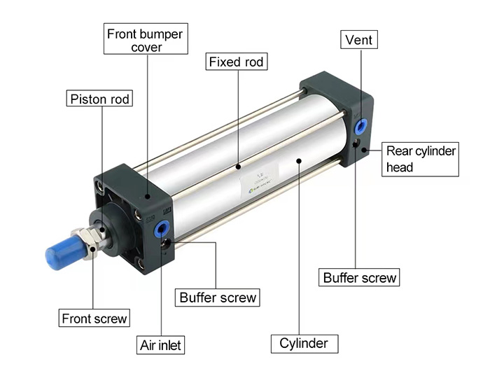
3. Structural Synergy: Cylinder Barrel and System Components
A cylinder barrel does not operate in isolation—it works in tandem with complementary components to deliver reliable actuation. Below is a breakdown of key interactions:
| Component | Role Relative to the Cylinder Barrel |
|-----------------|-------------------------------------------------------------------------------------------------------|
| Piston | A precision-fit disc that slides within the barrel’s bore; separates the barrel’s two chambers. Hydraulic/pneumatic pressure acts on the piston’s area to drive motion. |
| Piston Rod | Attached to the piston; extends through a sealed opening in one end cap to transmit linear force to the load. The barrel’s bore-to-rod alignment ensures minimal rod bending. |
| Seal Assemblies | Include rod seals (prevent fluid leakage past the rod), piston seals (isolate the two chambers), and wiper seals (keep contaminants out). The barrel’s smooth bore reduces seal abrasion. |
| End Caps | Threaded, bolted, or welded to the barrel’s ends; contain pressure and provide mounting points. Integrate ports for fluid/air inlet/outlet and guide bushings for the piston rod. |
4. Operating Principle: From Pressure to Motion
The cylinder barrel’s role in converting pressure to motion is consistent across hydraulic and pneumatic systems, with differences only in the working medium:
Step 1: Pressure Application
- Hydraulic Systems: A hydraulic pump delivers pressurized oil to one of the barrel’s chambers (e.g., the cap end chamber, which has a larger piston area) via a directional control valve.
- Pneumatic Systems: A regulator and solenoid valve supply filtered compressed air to one chamber of the barrel.
Step 2: Piston Actuation
Pressure in the targeted chamber creates a force imbalance on the piston (Force = Pressure × Piston Area). This imbalance pushes the piston linearly along the barrel’s bore, compressing the fluid/air in the opposite chamber (which is vented or returned to a reservoir via a second port).
Step 3: Force Transmission
As the piston moves, it drives the piston rod outward (extension) or inward (retraction), transferring mechanical force to the connected load (e.g., lifting a crane boom, closing a robotic gripper).
Step 4: Cycle Reset
For double-acting systems (the most common design), pressure is redirected to the opposite chamber, reversing the piston’s direction and completing the cycle. Single-acting systems rely on springs or external loads to reset the piston, with the barrel only containing pressure for one stroke.
5. Performance-Critical Factors for Cylinder Barrels
To avoid system failure (e.g., leaks, burst barrels, or seized pistons), three factors are non-negotiable:
1. Wall Thickness and Material Strength
Barrel wall thickness is calculated using the Lame equation (a standard for pressure vessels) to ensure it can withstand maximum operating pressure without plastic deformation. For example:
- A hydraulic barrel with a 4-in bore operating at 3,000 psi requires a 0.5-in wall thickness when made from SAE 4140 steel (yield strength = 100,000 psi).
- Using undersized walls risks “barrel expansion,” which damages seals and causes pressure loss.
2. Bore Precision and Surface Finish
- Concentricity: The barrel’s bore must be coaxial with its outer diameter (tolerance ≤ 0.002 in) to prevent piston binding.
- Surface Roughness: A smooth bore (Ra ≤ 0.4 μm) reduces friction between the piston seals and barrel, extending seal life by 50% or more compared to rough surfaces.
3. Corrosion and Wear Resistance
- Internal surfaces are often treated with hard chrome plating (5–10 μm thick) or gas nitriding (case depth 0.1–0.3 mm) to resist abrasion from hydraulic contaminants (e.g., metal particles) or pneumatic moisture.
- External coatings (e.g., powder coating, zinc plating) protect against environmental corrosion in outdoor or wet applications.
6. Maintenance Protocols for Extended Service Life
Cylinder barrels degrade over time due to wear, contamination, or seal failure—proactive maintenance is critical to avoid unplanned downtime. Key practices include:
1. Leak Detection
- Visual Inspection: Check for fluid/air leaks around end caps, rod seals, and port connections. Even small leaks (≤ 1 drop/min) indicate seal degradation or barrel damage.
- Pressure Testing: For hydraulic systems, isolate the barrel and apply 110% of maximum operating pressure; hold for 5 minutes—pressure loss > 5% indicates a breach.
2. Contamination Control
- Keep the barrel’s exterior and rod clean to prevent dirt from entering via wiper seals (use lint-free cloths and compatible solvents, e.g., isopropyl alcohol, to avoid seal swelling).
- Ensure hydraulic fluid is filtered (ISO 18/15 cleanliness standard) and pneumatic air is dried (dew point ≤ -40°F) to prevent internal corrosion or abrasive wear.
3. Wear Assessment
- Measure piston-to-bore clearance using a feeler gauge: excessive clearance (> 0.005 in for hydraulics, > 0.010 in for pneumatics) indicates barrel wear and requires replacement.
- Inspect the barrel’s internal surface for scratches, pitting, or corrosion—these can tear seals and cause irreversible pressure loss.
4. Preventive Maintenance Scheduling
- Heavy-duty hydraulic applications (e.g., construction): Inspect every 250 operating hours.
- Light pneumatic automation (e.g., packaging): Inspect every 1,000 operating hours.