Booster cylinders, also known as pressure booster cylinders, are advanced fluid power components designed to amplify air pressure to achieve high hydraulic output force with compact structural design. By combining pneumatic and hydraulic technologies, they leverage low-pressure compressed air to generate high-pressure hydraulic force, balancing the advantages of pneumatic systems (low cost, fast response) and hydraulic systems (high force, stable output). Widely used in precision assembly, metal forming, and automated manufacturing, booster cylinders play a crucial role in optimizing production efficiency, reducing energy consumption, and ensuring operational stability. This article provides a comprehensive technical analysis of booster cylinders, including their working principles, typical application scenarios, and systematic maintenance guidelines, serving as a practical reference for engineers, maintenance technicians, and production managers.
I. Core Working Principles of Booster Cylinders
Booster cylinders operate based on Pascal’s Law and the pressure amplification principle, integrating a pneumatic drive section and a hydraulic output section into a single unit. The key lies in converting low-pressure air energy into high-pressure hydraulic energy through area ratio differences, without the need for an independent hydraulic pump station. The working mechanism varies slightly by type but follows a consistent core logic, as detailed below:
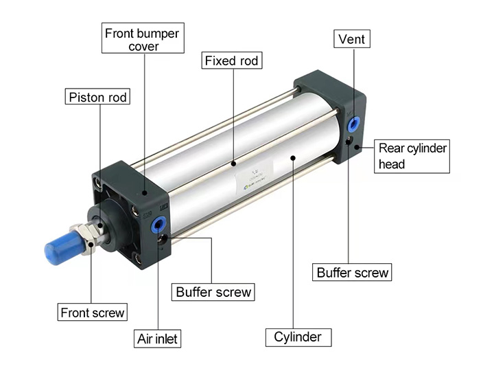
1. Basic Structural Composition
A standard booster cylinder consists of four core components, each contributing to pressure amplification and force output:
- Pneumatic Drive Section: Includes an air cylinder, piston, and air inlet/outlet valves. Compressed air (typically 0.4-0.8 MPa) acts on the pneumatic piston to provide driving force for the entire system.
- Hydraulic Output Section: Comprises a hydraulic cylinder, plunger, and hydraulic oil chamber. The hydraulic plunger is mechanically connected to the pneumatic piston, and its movement compresses hydraulic oil to generate high pressure.
- Pressure Amplification Unit: The core component determining boost ratio, formed by the area difference between the pneumatic piston and hydraulic plunger. The boost ratio = (Area of pneumatic piston) / (Area of hydraulic plunger), usually ranging from 5:1 to 50:1, enabling output pressure of 2-40 MPa.
- Control and Safety Components: Includes check valves, relief valves, pressure switches, and seals. Check valves maintain hydraulic pressure after boosting, relief valves prevent overpressure damage, and pressure switches enable automatic control of the working cycle.
2. Working Cycle Process
Booster cylinders operate in a cyclic manner, consisting of three key phases: pressure building, boosting output, and resetting. Taking the most common pneumatic-hydraulic booster cylinder as an example:
1. Pressure Building Phase: Low-pressure compressed air is introduced into the pneumatic drive section, pushing the pneumatic piston forward. The connected hydraulic plunger moves synchronously, compressing hydraulic oil in the closed oil chamber. Check valves prevent oil backflow, allowing pressure to gradually build up.
2. Boosting Output Phase: As the pneumatic piston continues to advance, hydraulic oil pressure increases proportionally to the boost ratio. When the set pressure is reached (detected by a pressure switch), the high-pressure hydraulic oil acts on the hydraulic cylinder piston, delivering the required output force for operations such as pressing, punching, or clamping. During this phase, the system maintains stable high pressure with minimal air consumption.
3. Resetting Phase: After completing the operation, the air direction is reversed by a solenoid valve, introducing compressed air to the opposite side of the pneumatic piston. The piston and hydraulic plunger retract to their initial positions, and the hydraulic oil chamber refills with oil through a one-way valve, preparing for the next working cycle.
3. Key Technical Parameters
The performance of booster cylinders is defined by critical parameters that guide selection for specific applications:
- Boost Ratio: Determines the maximum output pressure, calculated by the area ratio of the pneumatic piston to the hydraulic plunger. A higher ratio delivers higher output pressure but may reduce movement speed.
- Input Air Pressure: Typically 0.4-0.8 MPa; stable input pressure ensures consistent output performance.
- Output Hydraulic Pressure: Ranges from 2 MPa to 40 MPa, depending on the boost ratio and input air pressure.
- Output Force: Calculated as output pressure × effective area of the hydraulic piston, usually 10 kN to 500 kN.
- Stroke Length: Includes working stroke (for boosting output) and reset stroke, ranging from 5 mm to 500 mm based on application needs.
- Response Speed: Influenced by air flow rate, oil viscosity, and cylinder structure; faster than traditional hydraulic systems but slower than pure pneumatic cylinders.
II. Typical Application Scenarios of Booster Cylinders
Booster cylinders are widely adopted in industries requiring high force with compact equipment and low energy consumption, thanks to their advantages of no hydraulic pump station, energy saving, and easy integration. Typical application scenarios include:
1. Precision Assembly and Joining
In automotive, electronics, and electrical industries, booster cylinders are used for precision assembly operations that demand controlled high force without damaging workpieces:
- Automotive Manufacturing: Press-fitting of bearings, bushings, gears, and axle components; riveting of body panels and chassis parts. The stable output force ensures consistent assembly quality, avoiding workpiece deformation.
- Electronic Equipment: Precision pressing of connectors, terminals, and semiconductor components; bonding of circuit boards and electronic modules. The adjustable pressure and slow-speed output prevent damage to fragile electronic parts.
2. Metal Forming and Processing
For small-to-medium batch metal processing, booster cylinders provide cost-effective high-force solutions compared to large hydraulic presses:
- Punching and Blanking: Punching holes in thin metal sheets (steel, aluminum, copper) for hardware, electrical enclosures, and automotive parts. The fast response and high pressure ensure clean, burr-free cuts.
- Bending and Shaping: Bending thin-walled metal components, such as brackets, frames, and decorative parts. The uniform force distribution avoids uneven deformation of workpieces.
- Stamping and Embossing: Stamping logos, patterns, or serial numbers on metal surfaces; embossing of decorative metal products. The precise pressure control ensures clear, consistent patterns.
3. Clamping and Holding Systems
In machine tools, automated production lines, and mold processing, booster cylinders are used for high-pressure clamping to ensure workpiece stability during machining:
- Machine Tool Clamping: Clamping workpieces on CNC lathes, milling machines, and grinding machines. The self-locking function (maintained by check valves) ensures stable clamping even during power outages.
- Mold Clamping: Clamping small-to-medium sized molds in injection molding, die-casting, and stamping equipment. The compact design saves space compared to hydraulic clamping systems.
4. Other Industrial Applications
- Packaging Industry: High-pressure sealing of heavy-duty packaging (metal cans, plastic barrels); compression molding of packaging materials. Ensures tight seals to prevent leakage and extend product shelf life.
- Aerospace Components: Precision pressing of small aerospace parts (fasteners, connectors) that require high force and strict quality control. The clean, oil-free operation (with proper seals) meets aerospace standards.
- Hardware and Tool Manufacturing: Crimping of hydraulic hoses, cable lugs, and tool components; forging of small hardware parts. The adjustable output force adapts to different workpiece specifications.
III. Systematic Maintenance Guidelines for Booster Cylinders
Proper maintenance of booster cylinders is essential to ensure long service life, stable performance, and reduced downtime. The following guidelines cover daily inspection, regular maintenance, and fault troubleshooting:
1. Daily Inspection (Before and After Operation)
Conduct quick checks to identify potential issues early and prevent minor problems from escalating:
- Pressure and Air Supply: Verify that the input air pressure is within the recommended range (0.4-0.8 MPa). Check for air leaks in hoses, fittings, and valves using a soapy water solution; tighten loose connections or replace damaged parts promptly.
- Hydraulic Oil Level and Quality: Inspect the oil level in the hydraulic chamber (maintain between the minimum and maximum marks). Check oil quality—replace oil if it appears cloudy, discolored, or contains impurities (indicative of contamination or oxidation).
- Seal Integrity: Check for oil or air leaks around the piston rod, cylinder ends, and connectors. Damaged seals (O-rings, piston seals) cause pressure loss and reduced efficiency; replace them immediately.
- Operation Stability: Observe the cylinder’s movement during the working cycle—ensure smooth extension and retraction without jamming, abnormal noise, or pressure fluctuations. Abnormal sounds may indicate worn bearings or misalignment.
2. Regular Maintenance (Scheduled Based on Operating Hours)
Perform in-depth maintenance at fixed intervals (typically every 500-1,000 operating hours, or as recommended by the manufacturer) to maintain optimal performance:
- Hydraulic Oil Replacement: Drain old hydraulic oil completely, clean the oil chamber to remove sediment and impurities, and refill with the recommended oil grade (usually ISO VG 32 or VG 46 hydraulic oil). Replace the oil filter simultaneously to prevent contamination.
- Seal Replacement: Replace all worn or aging seals (O-rings, piston seals, rod seals) with genuine parts. Apply a thin layer of hydraulic oil to new seals before installation to reduce friction and prevent damage.
- Lubrication: Lubricate the pneumatic piston rod, guide rails, and moving parts with the recommended lubricant (compatible with hydraulic oil and seals). Avoid over-lubrication, which may cause oil accumulation and contamination.
- Valve and Switch Calibration: Inspect check valves, relief valves, and pressure switches for proper operation. Calibrate pressure switches to ensure accurate pressure detection; clean valve cores to remove debris that may cause blockages.
- Structural Inspection: Check for wear, corrosion, or deformation of the cylinder body, piston rod, and mounting brackets. Straighten or replace bent piston rods; repair corroded surfaces to prevent structural damage.
3. Fault Troubleshooting
Common faults in booster cylinders and their corresponding solutions are summarized below to minimize downtime:
Fault Phenomenon
Possible Causes
Solutions
Insufficient output pressure
1. Low input air pressure; 2. Air/oil leaks; 3. Clogged check valve; 4. Worn hydraulic plunger
1. Adjust input pressure to recommended range; 2. Repair leaks and replace seals; 3. Clean or replace check valve; 4. Replace hydraulic plunger
Slow cylinder movement
1. Insufficient air flow rate; 2. High oil viscosity (low temperature); 3. Clogged oil filter; 4. Misaligned piston rod
1. Increase air flow (replace larger hoses/fittings); 2. Heat oil or use lower viscosity grade; 3. Replace oil filter; 4. Align piston rod and lubricate guide parts
Cylinder fails to reset
1. Reverse air pressure insufficient; 2. Solenoid valve malfunction; 3. Piston stuck due to contamination; 4. Damaged reset spring
1. Check reverse air supply; 2. Clean or replace solenoid valve; 3. Disassemble and clean cylinder, remove contaminants; 4. Replace reset spring
Oil leakage
1. Worn/damaged seals; 2. Loose fittings; 3. Cylinder body cracks; 4. Overfilled hydraulic oil
1. Replace seals; 2. Tighten fittings; 3. Repair or replace cylinder body; 4. Drain excess oil to recommended level
Abnormal noise during operation
1. Lack of lubrication; 2. Misaligned piston rod; 3. Worn bearings/bushings; 4. Air in hydraulic oil
1. Lubricate moving parts; 2. Align piston rod; 3. Replace worn bearings/bushings; 4. Bleed air from hydraulic system
4. Long-Term Storage and Protection
For booster cylinders not in use for an extended period (more than 3 months):
- Drain hydraulic oil and clean the oil chamber; fill with anti-rust oil to prevent corrosion.
- Extend the piston rod slightly and apply anti-rust grease to the rod surface to protect against oxidation.
- Store the cylinder in a dry, well-ventilated area away from direct sunlight, high temperature, and corrosive gases.
- Cover air and oil ports with protective caps to prevent dust and debris from entering the system.
IV. Key Selection Considerations
To select the optimal booster cylinder for specific applications, consider the following factors to ensure compatibility and performance:
- Output Force and Pressure: Calculate the required force based on workpiece specifications, and select a cylinder with a boost ratio that meets the pressure demand (reserve 10-20% safety margin).
- Stroke Length: Choose a stroke that covers the maximum working distance, plus a small buffer margin to avoid over-stroke damage.
- Response Speed: Match the cylinder’s speed to production cycle requirements; adjust air flow rate or select a larger bore size for faster response.
- Environmental Conditions: For high-temperature, dusty, or corrosive environments, select cylinders with heat-resistant seals, dust covers, and corrosion-resistant materials (stainless steel components).
- Integration and Control: Ensure compatibility with existing pneumatic/hydraulic systems; select cylinders with appropriate control interfaces (solenoid valves, pressure switches) for automated operation.
V. Conclusion
Booster cylinders represent a versatile and efficient solution for high-force industrial applications, combining the simplicity of pneumatic systems with the high-pressure capability of hydraulic systems. Their compact design, energy-saving operation, and easy integration make them indispensable in precision assembly, metal processing, and automated manufacturing.
A thorough understanding of their working principles helps optimize application design, while adherence to systematic maintenance guidelines ensures long-term reliability and reduced operational costs. By selecting the right booster cylinder based on specific application requirements and maintaining it properly, engineers and production managers can enhance process efficiency, improve product quality, and gain a competitive edge in industrial operations.
As manufacturing technology advances, booster cylinders continue to evolve toward higher precision, faster response, and smarter control (e.g., integrated sensors for real-time pressure monitoring). Staying updated on these technological trends is essential for leveraging the full potential of booster cylinders in modern industrial systems.