Hydraulic systems serve as the primary actuation backbone for heavy machinery, construction equipment, and industrial automation—delivering high linear force (up to 10,000 kN) with precise positional control. At the heart of these systems lies the hydraulic cylinder, a mechanical actuator that converts hydraulic fluid pressure (typically 10–40 MPa, or 1,500–5,800 psi) into linear motion. Among its critical subcomponents, the hydraulic cylinder head (commonly termed the "cap-end head") is indispensable for maintaining system integrity, optimizing performance, and ensuring operational safety. This article explores the technical definition, engineering functions, design variations, and maintenance considerations of hydraulic cylinder heads, grounded in industry standards and material science principles.
1. Hydraulic Cylinder Fundamentals: Context for the Head
A hydraulic cylinder operates on Pascal’s principle (pressure equilibrium) and comprises five core subsystems. To contextualize the head’s role, below is a precise breakdown of key components:
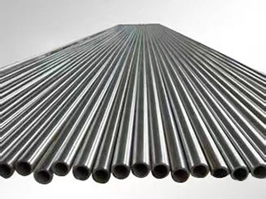
Barrel (cylinder tube): The pressure vessel housing the piston, typically manufactured from seamless carbon steel (AISI 1045) or stainless steel (AISI 316) with honed internal surfaces (Ra ≤ 0.4 μm) to minimize piston seal wear.
Piston: A cylindrical component (often with polyurethane or metal seals) that separates the cylinder’s rod-end and cap-end chambers, translating fluid pressure into linear force.
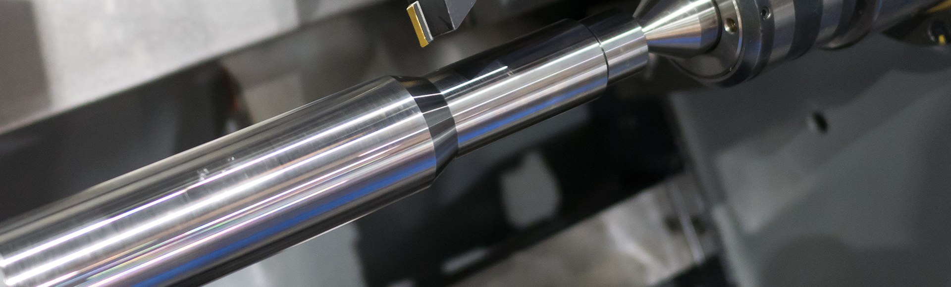
Piston rod: A high-strength shaft (AISI 4140, quenched and tempered to 28–32 HRC) connected to the piston, transmitting force to external loads; its surface is often hard-chromed (50–100 μm thickness) for abrasion resistance.
Rod-end cap: The component sealing the rod’s exit side, equipped with wiper seals to prevent contaminants from entering the cylinder.
Hydraulic cylinder head (cap-end head): The pressure-containing component sealing the barrel’s opposite end (cap side), integrating sealing, guiding, and pressure-bearing functionalities.
The cylinder head is engineered to perform three non-negotiable functions, each critical to hydraulic system reliability:
2.1 Fluid Sealing & Contamination Control
The head houses a seal assembly that prevents internal fluid leakage (between cap-end chamber and atmosphere) and external contamination ingress. Typical seal configurations include:
Primary pressure seals: U-cup seals (nitrile rubber/NBR for general service, fluoroelastomer/FKM for high temperatures ≤ 200°C) or energized PTFE seals (for low-friction, high-pressure applications ≥ 35 MPa).
Wiper seals: Polyurethane (PU) or PTFE wipers that scrape debris from the piston rod during retraction, complying with ISO 6195 for seal dimensional standards.
Static seals: O-rings (per AS568) or flat gaskets between the head and barrel, ensuring no leakage at the mating interface.
2.2 Piston Rod Guidance & Alignment
To prevent rod bending and uneven seal wear, the head incorporates a guide bushing (also called a wear bushing) that maintains concentricity between the rod and barrel. Guide materials are selected for low friction and high wear resistance:
Bronze alloys (e.g., CuSn10Pb10) for medium-load applications.
Thermoplastic composites (e.g., POM + glass fiber or PEEK) for high-speed, low-maintenance systems (coefficient of friction ≤ 0.15).
Metal-polymer bushings (e.g., steel-backed PTFE) for heavy-duty applications (load capacity ≥ 50 MPa).
2.3 Pressure Bearing & Structural Integrity
The head must withstand full system pressure (up to 70 MPa for high-pressure hydraulic circuits) without deformation or failure. Its design accounts for:
Material strength: For heavy-duty cylinders, heads are machined from forged AISI 4140 or AISI 4340 steel (tensile strength ≥ 1,000 MPa); for light-duty applications, aluminum alloy 6061-T6 (tensile strength ~310 MPa) is used.
Pressure vessel design: Compliance with ASME BPVC Section VIII (for pressure vessels) or ISO 4413 (hydraulic fluid power systems) to ensure wall thickness meets pressure rating requirements.
3. Design Variations of Hydraulic Cylinder Heads
Head designs are tailored to application requirements (pressure, maintenance access, environmental conditions) and include three primary configurations:
3.1 Threaded Heads (Cap-End Threaded Design)
Configuration: The head features external threads that mate with internal threads in the barrel (per ISO 6022 metric threads or UNC threads for imperial systems). A locknut or thread-locking compound (e.g., Loctite 243) prevents loosening under vibration.
Advantages: High pressure resistance (suitable for ≤ 50 MPa), compact design, and easy assembly/disassembly for small-to-medium cylinders.
Applications: Mobile hydraulics (e.g., excavator bucket cylinders), industrial presses, and agricultural machinery.
3.2 Welded Heads (Cap-End Welded Design)
Configuration: The head is permanently joined to the barrel via circumferential welding—typically gas metal arc welding (GMAW) per AWS D1.1 (carbon steel) or AWS D1.6 (stainless steel). Post-welding heat treatment (stress relieving) is performed to eliminate residual stresses.
Advantages: Maximum structural rigidity, zero thread leakage risk, and suitability for thick-walled barrels (>10 mm).
Applications: Heavy-duty construction equipment (e.g., crane lift cylinders), offshore hydraulic systems, and mining machinery (harsh, high-vibration environments).
3.3 Bolted Heads (Cap-End Flanged Design)
Configuration: The head has a flange with drilled holes, secured to a matching flange on the barrel using high-tensile bolts (ISO 898-1 Class 10.9 or SAE J429 Grade 8). A metal gasket or O-ring ensures a seal between flanges.
Advantages: Easy maintenance (no thread disassembly), compatibility with large-diameter cylinders, and replaceability without barrel modification.
Applications: Large industrial cylinders (e.g., steel mill hydraulic presses), marine hydraulics, and power generation systems (where downtime must be minimized).
4. Criticality of the Cylinder Head to System Performance
The cylinder head directly impacts three key performance metrics for hydraulic systems:
4.1 Energy Efficiency
Uncontrolled fluid leakage through the head (e.g., worn seals) reduces system efficiency by 15–25% (per Hydraulic Institute data), as the pump must compensate for lost flow. A well-sealed head ensures fluid is directed to the piston, maximizing force output per unit of hydraulic power.
4.2 Service Life & Reliability
Wear resistance: A high-quality guide bushing reduces rod wear, extending piston rod life by 2–3x.
Corrosion resistance: Heads for harsh environments (e.g., marine, chemical processing) are coated with zinc-nickel plating (per ASTM B841) or painted with epoxy-polyester powder coating to prevent pitting corrosion.
Fatigue resistance: For reciprocating cylinders (e.g., injection molding machines), the head’s design minimizes stress concentrations, preventing fatigue failure (tested per ISO 10771 for cyclic loading).
4.3 Maintenance Accessibility
Bolted heads enable seal replacement in 1–2 hours (vs. 4–6 hours for welded heads), reducing maintenance downtime by 60–70%. Threaded heads, while less accessible than bolted designs, still allow seal servicing without barrel replacement.
5. Common Failure Modes & Mitigation Strategies
Cylinder head failures often stem from poor design, material selection, or maintenance practices. Below are key issues and engineering solutions:
5.1 Seal Leakage
Root causes: Seal degradation (thermal aging, chemical attack), improper seal installation (twisting), or guide bushing wear (rod misalignment).
Mitigation: Use application-matched seals (e.g., FKM for oil & high temps, EPDM for water-based fluids), follow ISO 13715 seal installation guidelines, and inspect seals quarterly (or per 500 operating hours).
5.2 Corrosion & Material Degradation
Root causes: Exposure to saltwater (marine), chemicals (industrial), or humidity (outdoor storage).
Mitigation: Select corrosion-resistant materials (AISI 316 for stainless steel heads, aluminum 7075-T6 for lightweight applications), apply protective coatings (e.g., ceramic coating for high-abrasion environments), and conduct periodic corrosion testing (per ASTM B117 salt spray testing).
5.3 Rod Misalignment & Guide Bushing Wear
Root causes: Improper cylinder mounting (parallelism error >0.1 mm/m), external side loads on the rod, or contaminated lubrication.
Mitigation: Use self-aligning mounts (e.g., spherical bearings), limit side loads to ≤ 5% of rated force (per ISO 6020-2), and lubricate guide bushings with grease (NLGI Grade 2) every 1,000 operating hours.
6. Special Considerations for Reciprocating Hydraulic Cylinders
In reciprocating cylinders (the most common type), the head’s role is amplified due to cyclic rod movement:
Dynamic sealing: The head’s seal assembly must accommodate rod velocities up to 1 m/s without leakage—requiring low-friction seals (e.g., PTFE-energized) and wiper seals that prevent air ingestion (which causes cavitation).
Positional accuracy: For precision applications (e.g., CNC machine tools), the head’s guide bushing ensures rod concentricity, enabling positional accuracy of ±0.02 mm (when paired with linear position sensors like LVDTs).