In the dynamic landscape of fluid power systems, hydraulic cylinder barrels stand as the unsung backbone that translates hydraulic pressure into precise, high-force linear motion. From heavy-duty construction machinery to high-precision industrial robots, the performance, durability, and reliability of hydraulic systems hinge entirely on the design, material, and selection of cylinder barrels. Unlike auxiliary components that can be easily replaced, a suboptimal cylinder barrel design or mismatched selection can lead to catastrophic system failures, unplanned downtime, and soaring maintenance costs. This article demystifies the intricate structure of hydraulic cylinder barrels, elaborates on their working principles, and provides a systematic selection guide tailored to diverse industrial applications, empowering engineers to make informed decisions for their specific fluid power needs.
1. Structural Anatomy of Hydraulic Cylinder Barrels
A
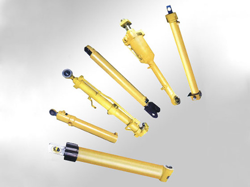
hydraulic cylinder barrel is not a monolithic component but a sophisticated assembly of interconnected parts, each engineered to fulfill a unique function while maintaining synergy with the entire system. The core structure consists of five critical modules, as detailed below:
1.1 Cylinder Barrel (Housing)
The cylinder barrel is the outermost cylindrical shell that houses the piston and hydraulic fluid, serving as the primary pressure-bearing component. Its design is governed by the maximum operating pressure of the hydraulic system, typically ranging from 16 MPa (low-pressure systems) to 40 MPa (high-pressure heavy machinery).
- Materials: For general industrial applications, seamless carbon steel tubes (e.g., 45# steel, 20# steel) are preferred due to their high tensile strength (≥550 MPa) and cost-effectiveness. In corrosive environments (e.g., marine, chemical processing), stainless steel (304/316) or aluminum alloy (6061-T6) is adopted to resist rust and chemical erosion. For ultra-high-pressure applications (≥63 MPa), alloy steel tubes with quenching and tempering treatment are used to enhance yield strength and fatigue resistance.
- Key Design Parameters: Wall thickness is calculated using the Lame equation to ensure the barrel can withstand internal pressure without plastic deformation. The inner surface finish is critical—precision honing is mandatory to achieve a roughness (Ra) of 0.05–0.2 μm, minimizing friction between the piston seal and the barrel wall and extending seal service life.
1.2 Piston & Piston Rod Assembly
The piston divides the cylinder barrel into two chambers (rod chamber and cap chamber) and converts hydraulic pressure into mechanical force. The piston rod transmits this force to the external load, requiring both rigidity and surface hardness.
- Piston: Typically made of cast iron or engineering plastics (e.g., PTFE-filled nylon), it is equipped with dual-seal systems (e.g., O-rings + wear rings) to prevent internal leakage between the two chambers. The piston’s outer diameter tolerance is controlled to H9 to ensure a tight fit with the barrel inner wall.
- Piston Rod: Manufactured from high-strength alloy steel (e.g., 40Cr), its surface undergoes hard chrome plating (thickness 0.02–0.05 mm) and polishing to achieve a hardness of ≥60 HRC, resisting wear and corrosion from external contaminants. The rod’s straightness error is limited to 0.1 mm/m to avoid bending during reciprocating motion.
1.3 End Caps & Mounting Mechanisms
End caps seal the two ends of the cylinder barrel and provide mounting interfaces for integrating the cylinder into the host equipment. Two main types of end caps are used:
- Welded End Caps: Permanent, high-strength connection suitable for heavy-load applications (e.g., excavator boom cylinders). The weld joint must undergo ultrasonic testing (UT) to eliminate internal defects like porosity and cracks.
- Flanged End Caps: Detachable design using bolts, facilitating maintenance and piston replacement. Common in industrial automation systems where frequent disassembly is required.
- Mounting Types: The selection of mounting mechanisms depends on the load direction and stroke length:
- Flange Mount (front/rear): Ideal for heavy, stationary loads, providing maximum stability.
- Clevis Mount: Suitable for dynamic, oscillating loads (e.g., agricultural machinery).
- Tie-Rod Mount: Cost-effective for standard industrial cylinders with short to medium strokes.
1.4 Sealing & Dust-Exclusion Systems
Seals are the lifeline of hydraulic cylinder barrels, preventing internal fluid leakage and external contamination. A robust sealing system comprises three layers:
- Primary Seals: U-cup seals or V-packing seals for rod chambers; piston seals (e.g., Glyd rings) for cap chambers, designed to withstand high pressure and reciprocating motion.
- Wear Rings: Made of bronze or PTFE, they reduce metal-to-metal contact between the piston/rod and barrel, minimizing wear.
- Dust Rings: Installed on the rod end cap, they scrape off dust, gravel, and moisture from the piston rod surface before it retracts into the barrel, preventing seal damage and fluid contamination.
1.5 Cushioning Mechanisms
For cylinders with long strokes or high operating speeds (≥0.5 m/s), cushioning mechanisms are integrated into the end caps to decelerate the piston before it reaches the end of the stroke, reducing impact and noise.
- Fixed Cushioning: Uses a small-diameter orifice to restrict fluid flow during the final stage of piston movement, suitable for low-speed, light-load systems.
- Adjustable Cushioning: Equipped with a needle valve to regulate the orifice size, allowing engineers to fine-tune the deceleration rate according to specific application requirements.
2. Working Principles of Hydraulic Cylinder Barrels
2.1 Single-Acting Cylinders
Fluid is supplied to only one chamber (cap chamber), pushing the piston rod outward. The return stroke is driven by an external force (e.g., gravity, springs). This design is simple and cost-effective, commonly used in applications like dump truck lifting systems and jacks.
2.2 Double-Acting Cylinders
Fluid can be supplied to both the rod and cap chambers, enabling bidirectional motion of the piston rod. The force output differs between the extension and retraction strokes: the extension force is higher (larger effective area) than the retraction force (smaller effective area due to the piston rod occupying space). Double-acting cylinders are the most widely used type in industrial automation, robotics, and construction machinery.
3. Systematic Selection Guide for Hydraulic Cylinder Barrels
Selecting the right hydraulic cylinder barrel requires a step-by-step approach that aligns with the application’s operating conditions, load requirements, and environmental constraints. The following five-step framework ensures optimal selection:
3.1 Define Core Operating Parameters
- Determine Maximum Load & Pressure: Calculate the required output force using the load weight and mechanical leverage ratio. Then select the hydraulic system pressure (e.g., 25 MPa for medium-load applications) and compute the piston diameter using the force formula. For example, a 50 kN load at 25 MPa requires a piston diameter of approximately 50 mm.
- Confirm Stroke Length: The stroke length is the maximum distance the piston rod travels. Add a 5–10% margin to the required stroke to account for installation errors and cushioning mechanisms. For precision positioning applications (e.g., robotic arms), select cylinders with adjustable stroke limits.
- Specify Operating Speed: The piston speed is determined by the fluid flow rate and piston area ($v = Q/A$). For high-speed applications (>0.5 m/s), prioritize cylinders with cushioning systems and high-performance seals to avoid heat generation and seal wear.
3.2 Match Materials to Operating Environment
| Operating Environment | Recommended Barrel Material | Key Advantages |
|-----------------------|-----------------------------|----------------|
| General Industrial | Seamless Carbon Steel (45#) | High strength, low cost |
| Corrosive (Marine/Chemical) | Stainless Steel (316) | Excellent corrosion resistance |
| Lightweight Applications (Aerospace/Robots) | Aluminum Alloy (6061-T6) | Low density, good thermal conductivity |
| Ultra-High-Pressure (≥63 MPa) | Quenched Alloy Steel | Superior fatigue resistance |
3.3 Select Sealing Systems Based on Fluid & Temperature
The seal material must be compatible with the hydraulic fluid and operating temperature range:
- Mineral Oil Hydraulic Fluid: Use nitrile rubber (NBR) seals, suitable for temperatures between -20℃ and 100℃.
- Synthetic Hydraulic Fluid (e.g., phosphate ester): Use fluororubber (FKM) seals, resistant to high temperatures (up to 200℃) and chemical degradation.
- Low-Temperature Environments (≤-30℃): Use silicone rubber (VMQ) seals to maintain flexibility.
3.4 Choose Mounting Mechanisms for Load Dynamics
- Static Loads (e.g., clamping devices): Front/rear flange mounting for maximum stability.
- Dynamic Oscillating Loads (e.g., excavator arms): Clevis or trunnion mounting to accommodate angular movement.
- Long-Stroke Applications (e.g., conveyor systems): Tie-rod mounting for easy assembly and maintenance.
3.5 Avoid Common Selection Pitfalls
- Overlooking Corrosion Resistance: Using carbon steel barrels in marine environments leads to rapid rusting and seal failure—always prioritize stainless steel or coated materials.
- Ignoring Cushioning Requirements: High-speed cylinders without cushioning mechanisms cause severe impact, shortening the service life of end caps and host equipment.
- Underestimating Surface Finish: A rough inner surface (Ra > 0.4 μm) accelerates seal wear, leading to frequent fluid leakage and system inefficiency.
4. Key Application Fields & Selection Priorities
Hydraulic cylinder barrels are ubiquitous in industries where high force, precise positioning, and reliable operation are essential. Below are the selection priorities for three core application scenarios:
4.1 Construction & Agricultural Machinery
- Requirements: High pressure (31.5–40 MPa), heavy load, harsh operating conditions (dust, vibration, temperature fluctuations).
- Selection Priorities: Welded end caps for high strength; alloy steel barrels with quenching treatment; chrome-plated piston rods; robust dust exclusion systems.
4.2 Industrial Automation & Robotics
- Requirements: Medium pressure (16–25 MPa), precise positioning, low noise, compact design.
- Selection Priorities: Flanged end caps for easy integration; aluminum alloy barrels for lightweight design; adjustable cushioning mechanisms; high-precision honed inner surfaces (Ra ≤ 0.1 μm).
4.3 Marine & Chemical Processing Equipment
- Requirements: Corrosion resistance, medium pressure (10–20 MPa), compliance with hygiene standards (for food/chemical industries).
- Selection Priorities: Stainless steel (316) barrels; PTFE seals compatible with chemical fluids; polished inner surfaces to prevent fluid contamination.