Hydraulic Cylinder Structure Principle, Classification, Application, and Maintenance Guide
Release time:2025-08-03 Visits:303
Hydraulic Cylinder Structure Principle, Classification, Application, and Maintenance Guide
As the core actuating element of a hydraulic system, the hydraulic cylinder converts hydraulic energy into mechanical energy to achieve linear reciprocating motion or swinging. With its simple structure, stable operation, and strong load - bearing capacity, it is widely used in construction machinery, metallurgical equipment, automobile manufacturing, and other fields. This article will systematically analyze the composition structure, type classification, selection parameters, and common fault solutions of hydraulic cylinders.
I. Working Principle and Core Components of Hydraulic Cylinders
Based on Pascal's principle, a hydraulic cylinder drives the piston to move through the pressure change of hydraulic oil in a closed cavity and outputs thrust and pull force. The core components include:
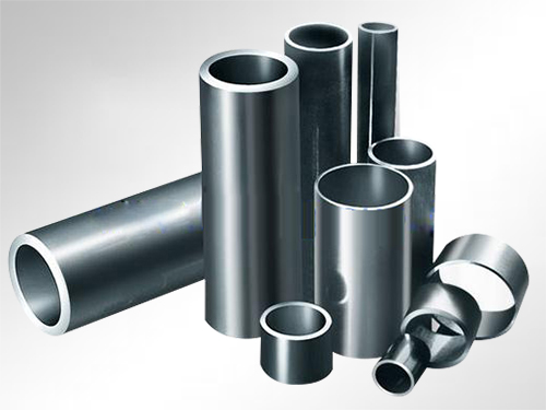
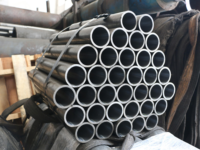
1. Cylinder Barrel and End Cover: Made of high - strength seamless steel pipes, the interior is precisely honed. Together with the end cover, they form a sealed cavity. The main materials are No. 45 steel (for high - pressure environments) or No. 20 steel (for low - pressure scenarios) to ensure pressure resistance and service life.
2. Piston and Piston Rod: The piston converts hydraulic energy into mechanical energy, and the piston rod transmits power to external mechanisms. They are often made of No. 35/45 steel or wear - resistant cast iron, and the surface is treated with high - frequency quenching to a hardness of 45 - 55 HRC to enhance wear resistance.
3. Sealing System: It includes dust seals, guide sleeves, and multi - stage seals to prevent oil leakage and the intrusion of contaminants. The sealing material should be selected according to the working temperature (- 30°C to 120°C) and medium compatibility (such as mineral oil and water - based fluids).
4. Buffering Device: Through the design of throttle holes or variable cross - sections, it converts the kinetic energy at the end of the piston into heat energy to reduce impact noise. Configuring a buffer can extend the service life of the cylinder body by more than 30%.
5. Exhaust Valve: Usually located at the highest point of the cylinder body, it is used to expel the air mixed in the oil to avoid system crawling or pressure fluctuations.
II. Four Major Classifications and Application Scenarios of Hydraulic Cylinders
1. Piston Hydraulic Cylinder
- Single - piston - rod Type: Suitable for one - way load scenarios (such as machine tool feed systems), with a thrust range of 5 - 500 tons.
- Double - piston - rod Type: Designed for bidirectional constant - speed movement, it is mostly used in the mold - clamping device of injection molding machines.
2. Telescopic Hydraulic Cylinder
With a sleeve structure of more than three stages, the extended length can reach 5 times that of the retracted state. It is used in scenarios with limited space, such as dump truck lifting and fire - fighting ladders.
3. Plunger Cylinder
There is no matching requirement between the plunger and the cylinder barrel. It is particularly suitable for long - stroke (>10 meters) vertical lifting, such as hydraulic lifting platforms.
4. Swing Hydraulic Cylinder
The single/double - vane structure can achieve a swing within 270°, with a torque output of up to 20,000 N·m. It is used in ship steering gears and robot joints.
III. Key Selection Parameters and Design Specifications
1. Pressure Rating: According to ISO standards, it is divided into 16 MPa (light - duty), 25 MPa (medium - duty), and 31.5 MPa (heavy - duty). A 20% safety margin should be reserved.
2. Cylinder Bore - Piston Rod Diameter Ratio: The conventional ratio is 1.33:1 (thrust type) or 2:1 (speed type), which directly affects the output force and movement speed.
3. Stroke Accuracy: For cylinders used in precision machine tools, the straightness error needs to be controlled within 0.05 mm/m. A displacement sensor is used for closed - loop control.
4. Installation Method: It includes flange type (radial load ≤ 10 kN), earring type (swing angle ±15°), and hinge - shaft type (multi - degree - of - freedom system).
IV. Common Fault Diagnosis and Maintenance Strategies
1. External Leakage Treatment
- Scratches on the piston rod: Replace the rod body with a Cr coating (thickness 0.02 - 0.05 mm).
- Aging of seals: Replace them regularly (the recommended cycle is 2000 working hours).
2. Internal Leakage Inspection
- Failure of piston seals: Detect by the pressure test method. If the leakage amount is more than 5%, immediate maintenance is required.
- Deformation of the cylinder barrel: Detect the ovality with a laser caliper (if it is more than 0.1 mm, honing repair is required).
3. Prevention of Structural Damage
- Flange fracture: Optimize the R - angle transition (radius ≥ 5 mm) to eliminate stress concentration.
- Cracks at the cylinder bottom: Use finite element analysis to optimize the wall thickness, and the fatigue life can be improved by 40%.
4. Cavitation Protection
Control the oil temperature below 60°C, select hydraulic oil with good defoaming properties, and keep the flow velocity at the oil inlet less than 1.5 m/s.
V. Technological Innovation and Development Trends
Currently, hydraulic cylinders are developing towards intelligence. Intelligent cylinders integrated with pressure/temperature/displacement sensors can monitor the working status in real - time, and the predictive maintenance system can reduce the fault downtime rate by 70%. Nano - coating technology can triple the wear resistance of the piston rod, and the ceramic - matrix composite cylinder body can reduce the weight by 45% while increasing the pressure - bearing capacity by 30%.
Through scientific selection, standardized maintenance, and technological innovation, hydraulic cylinders will continue to play an irreplaceable role in the era of Industry 4.0. Users need to match the product specifications according to specific working - condition parameters and establish a regular inspection system to maximize equipment efficiency.