Hydraulic Cylinder Structure Analysis and Selection Guide: A Comprehensive Interpretation from Principle to Application
Release time:2025-06-22 Visits:327
Hydraulic Cylinder Structure Analysis and Selection Guide: A Comprehensive Interpretation from Principle to Application
As the core executive component of the hydraulic system, the hydraulic cylinder undertakes the crucial task of converting hydraulic energy into mechanical energy and is widely used in fields such as construction machinery, industrial equipment, and agricultural machinery. Its working principle is based on the change of the sealed volume. Through the pressure transmission of hydraulic oil in the closed cavity, the piston is driven to achieve linear or oscillating motion. This article will conduct a systematic analysis from four dimensions: structural composition, classification methods, selection factors, and maintenance essentials.
I. Core Structural Composition of the Hydraulic Cylinder
1. Cylinder Block Assembly
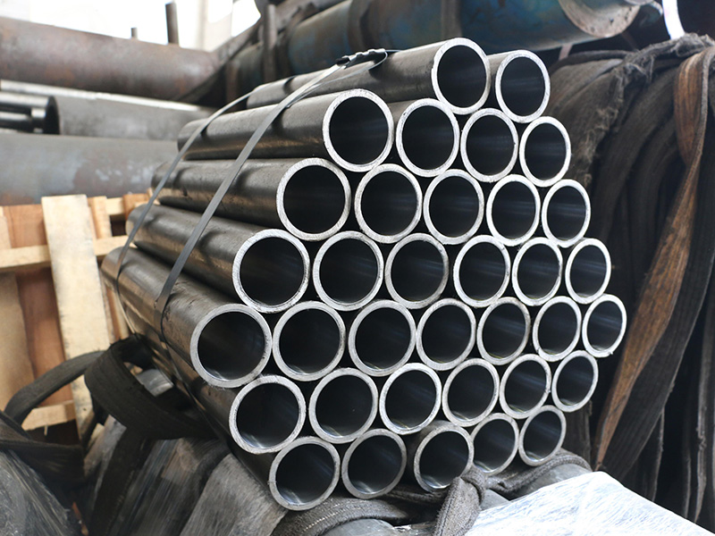
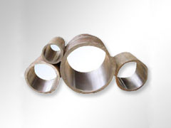
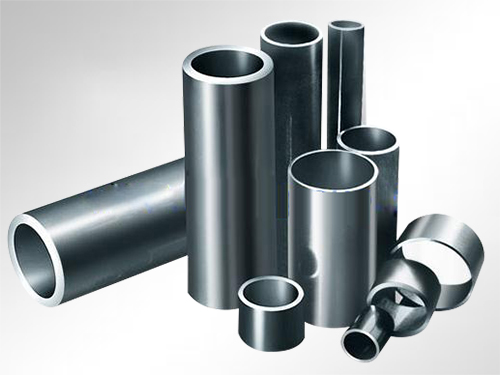
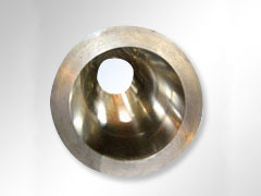
As the main structure, the cylinder barrel is usually made of high - strength seamless steel pipes. The inner wall needs to be precisely processed (such as honing or rolling processes) to reduce frictional resistance and improve sealing performance. The front and rear end covers are connected by flanges or threads to form a closed pressure chamber. The materials are mostly rolled steel or cast iron to withstand high - pressure environments.
2. Piston Assembly
The combination of the piston and the piston rod is the core unit of power transmission. The piston is usually made of cast iron or alloy steel and is fixed to the piston rod by means of threads, half - rings, or welding. The surface of the piston rod is treated by carburizing and quenching, chrome plating, etc., with both wear resistance and corrosion resistance.
3. Sealing System
The sealing device includes two types: static sealing (such as between the end cover and the cylinder barrel) and dynamic sealing (such as between the piston and the cylinder barrel). Commonly used materials include nitrile rubber, polyurethane, etc. High - quality seals can effectively prevent hydraulic oil leakage and ensure stable pressure transmission.
4. Auxiliary Devices
- Buffer Device: Through a throttle valve or a variable - aperture design, the piston speed is reduced at the end of the stroke to avoid mechanical collision.
- Exhaust Valve: It eliminates the air mixed into the system and eliminates vibration or crawling phenomena during operation.
II. Classification and Application Scenarios of Hydraulic Cylinders
According to the differences in motion forms and structures, hydraulic cylinders can be divided into three major categories:
1. Piston Hydraulic Cylinders
- Single - Rod Type: It is suitable for scenarios with asymmetric thrust requirements (such as the machine tool feed system), and the return stroke requires external loads or spring forces.
- Double - Rod Type: It outputs force symmetrically at both ends and is commonly used in clamping devices or balancing mechanisms.
2. Plunger Hydraulic Cylinders
The plunger only bears pressure in one direction and needs to cooperate with an external mechanism to achieve the return stroke. It is suitable for long - stroke and high - load scenarios (such as ship steering gears).
3. Multi - stage Telescopic Cylinders
It uses a nested sleeve structure and can achieve an ultra - long stroke in a limited installation space. It is commonly found in the lifting systems of dump trucks.
III. Key Parameters for Hydraulic Cylinder Selection
1. Pressure Rating: Select specifications of 16MPa, 25MPa, or 31.5MPa according to the system working pressure, and a 20% safety margin should be reserved.
2. Installation Form: The tie - rod type is suitable for compact spaces, the ear - ring type is convenient for oscillating installation, and the hinge - shaft type is suitable for rotating mechanisms.
3. Stroke and Speed: Calculate the ratio of the piston rod diameter to the cylinder diameter in combination with the load movement distance and the system flow to avoid the risk of cavitation.
4. Environmental Adaptability: In a corrosive environment, it is recommended to use a stainless - steel cylinder block or nickel - plating treatment. In high - temperature working conditions, fluororubber seals should be used.
IV. Common Faults and Maintenance Strategies
1. Cylinder Wall Cracks: They are mostly caused by the concentration of fatigue stress. Regularly check the stress distribution at the transition arc of the flange.
2. Seal Failure: It is recommended that the replacement cycle does not exceed 5000 working hours. Avoid twisting or scratching the sealing ring during installation.
3. Cavitation Damage: Keep the cleanliness of the hydraulic oil (below NAS 8 level) and control the oil temperature in the range of 50°C ± 10°C.
4. Abnormal Buffering: Regularly clean the impurities in the throttle hole, check the wear of the buffer sleeve, and replace ceramic composite parts if necessary.
When purchasing a hydraulic cylinder, it is necessary to clarify the load characteristics, working frequency, and environmental conditions of the equipment, and give priority to suppliers who provide pressure test reports and material certifications. Through scientific selection and maintenance, the service life of the hydraulic cylinder can be extended by more than 30%, significantly reducing the risk of equipment downtime.