Comprehensive Guide to Hydraulic Cylinder Design: Analysis of Core Principles and Standardized Processes
Comprehensive Guide to
Hydraulic Cylinder Design: Analysis of Core Principles and Standardized Processes
As a core component of the hydraulic system, the design of the hydraulic cylinder needs to balance performance, reliability, and economy. This article will systematically elaborate on the key principles, standard processes, and technical specifications that must be followed in the design process to help engineers efficiently complete structural optimization.
Ten Core Principles of Hydraulic Cylinder Design
1. Power Output and Motion Control
Ensure that the hydraulic cylinder can stably output the preset thrust or pull force and precisely control the motion speed and stroke. The piston area needs to be determined through load calculation, and the cylinder diameter size needs to be matched with the system pressure. At the same time, the influence of inertial force on speed should be considered.
2. Triple Guarantee of Structural Strength
The cylinder body should be made of high - strength materials such as No. 45 steel and its bearing capacity should be improved through heat treatment. The key indicators include:
- The wall thickness of the cylinder barrel should meet the working pressure of over 20 MPa.
- The ratio of the piston rod diameter to the stroke should be ≤ 1:10 to prevent longitudinal bending.
- The strength of the end - cover connection part should be checked. Usually, flange - type or threaded connections are used.
3. Compact and Lightweight Design
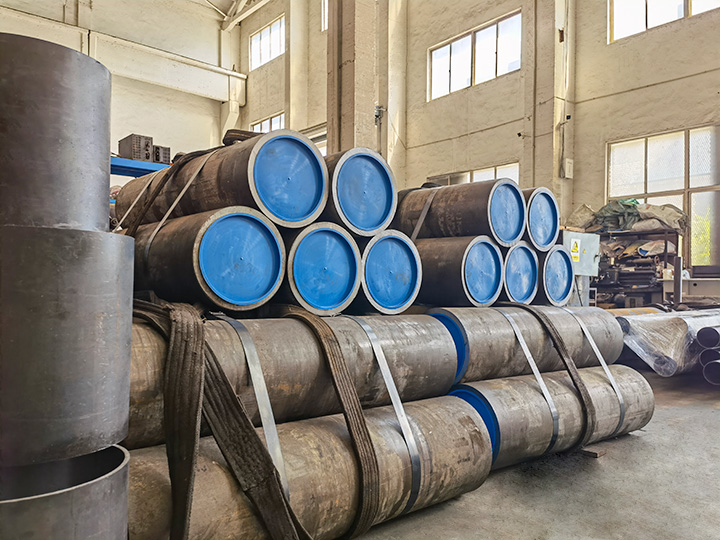
On the premise of meeting the strength requirements, cold - drawn seamless steel tubes should be preferred as the base material for the cylinder barrel. Through the precision honing process, the roughness of the inner hole should be controlled within Ra0.4μm, which can both reduce the size and ensure the sliding accuracy.
4. Modular Sealing System
A combined sealing scheme is adopted:
- Piston sealing: Polyurethane U - ring + Teflon Glide Ring.
- Rod sealing: Step - type dust seal + Guide ring.
- Static sealing: Metal wound gasket.
5. Dynamic Buffering Technology
For working conditions with a speed > 0.5 m/s, a multi - stage throttling buffer device should be configured. Smooth braking can be achieved through an adjustable throttle valve, reducing the impact load by over 30%.
6. Environmental Adaptability Design
- In a dusty environment: Add a double - lip dust seal.
- In high - temperature working conditions: Use fluororubber seals.
- In a corrosive medium: Hard - chrome plating should be applied to the inner wall of the cylinder barrel.
7. Application of Standardized Components
Standard cylinder diameters (φ32/40/50, etc.) in accordance with ISO6020/6022 should be preferred, and piston rods should be graded according to DIN/ISO standards (such as DIN2391 precision tubes).
Nine - Step Standardized Design Process
Stage 1: Definition of Basic Parameters
- Collect core parameters such as the maximum working load, stroke range, and operating frequency.
- Determine the installation method (trunnion - type/flange - type/foot - frame type).
Stage 2: Calculation of the Power System
1. Calculation of the piston diameter:
\( D=\sqrt{\frac{4F}{\pi P}} \)
(F: Output force, P: System pressure)
2. Flow matching:
\( Q = Av/612 \)
(A: Piston area, v: Motion speed)
Stage 3: Structural Design
- Verification of the cylinder barrel wall thickness:
\( t\geq\frac{PD}{2\sigma} \)
(σ: Allowable stress of the material)
- Check of the piston rod stability:
The Euler formula is applied to calculate the critical load.
Stage 4: Configuration of the Auxiliary System
- Buffer device: Selection between plunger - type and clearance - type buffers.
- Exhaust valve: Install an automatic exhaust component at the top.
- Sensor integration: Integrate a magnetic - ring - type displacement detection device.
Stage 5: Planning of the Manufacturing Process
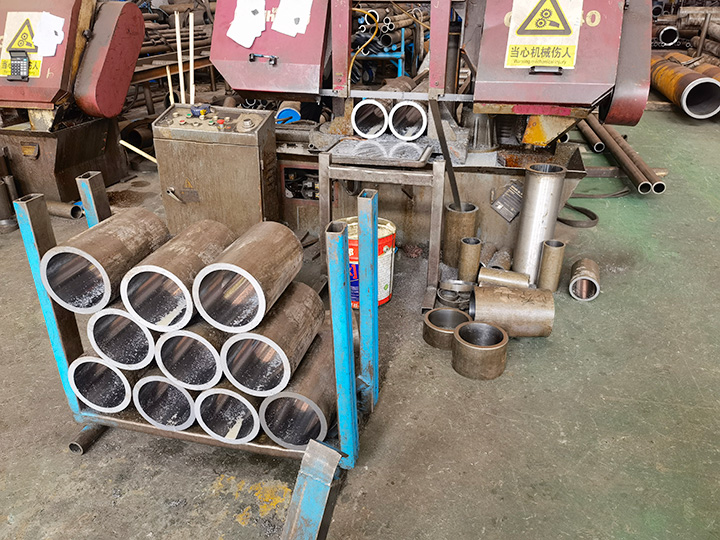
1. Cylinder barrel processing:
Rough boring → Fine reaming → Rolling (Surface hardness ≥ HRC60)
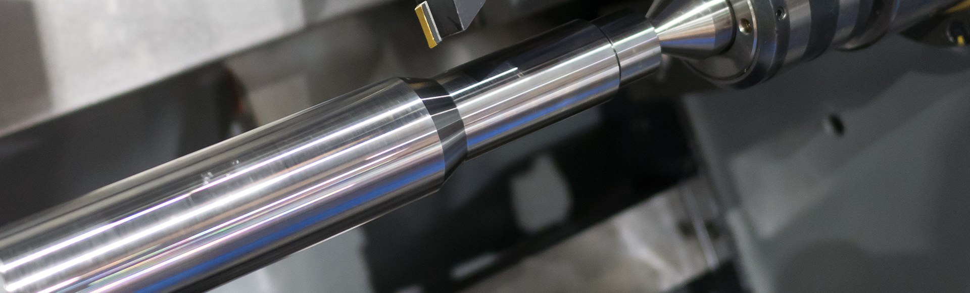
2. Piston rod treatment:
Quenching and tempering → Chrome plating (Coating thickness 0.03 - 0.05 mm) → Super - finishing grinding
Technical Specifications for Key Components
1. Cylinder Block Assembly
- Material: Cold - drawn seamless steel tubes (No. 20/No. 45)
- Straightness: ≤ 0.08 mm/1000 mm
- Inner hole tolerance: H8 - H9
2. Piston System
- Guide band width: 0.3 - 0.5 times the cylinder diameter
- Fit clearance: 0.05 - 0.15 mm (To maintain the oil film)
3. Sealing System
- Operating temperature: - 30℃~ + 200℃
- Pressure resistance level: ≥ 1.5 times the system pressure
By systematically applying these design criteria, the service life of the hydraulic cylinder can be increased by 30% - 50%. It is recommended to detect the sealing condition every 5000 working hours and implement preventive maintenance on the key fit dimensions.